In powder pressing, the ability to produce parts accurately is only one part of the productivity equation. As production trends shift from long, stable runs towards more varied order profiles, time and consistency of changeover are becoming increasingly important.
Each change from one tooling and powder system to another affects machine availability, labour planning and the stability of production restart.
This shift places new focus on one of the most critical and often most underestimated stages in powder pressing: the part changeover.
Retooling a press from one die set and powder system to another remains, in many operations, a largely manual process. It requires experienced personnel, careful cleaning, correct tooling installation and accurate transfer of process parameters. When carried out under time pressure, it can become a major source of downtime, quality variation and startup scrap.
DORST UPTIME: Automating product changeover in powder pressing

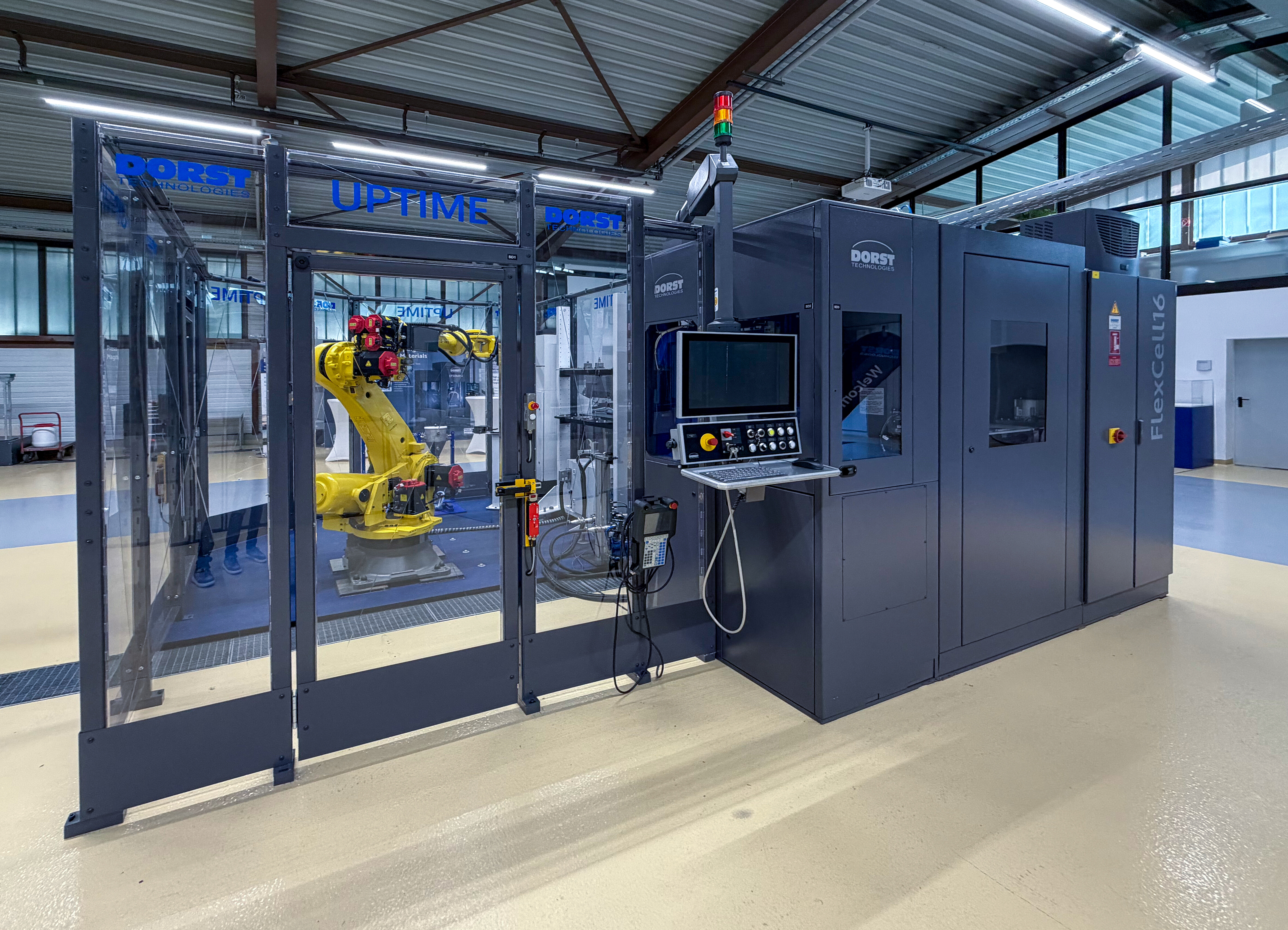
Dorst Technologies GmbH, headquartered in Kochel am See, Germany, has long supplied powder pressing and forming technologies for applications ranging from technical ceramics and cemented carbides to structural PM parts.
To address the growing challenge of changeover efficiency, the company has developed UPTIME, an automated part-changeover system that uses a robot, tool storage and integrated controls to automatically remove and install tooling and powder-feeding systems in a powder press.
By integrating changeover into the production cell’s controlled sequence, UPTIME replaces a manual, operator-dependent procedure with a controlled repeatable process. The objective is to reduce downtime, improve process consistency and support more flexible production planning as batch sizes fall and part variety increases.
Why manufacturers are automating part changeover
As powder pressing systems become more advanced, attention is increasingly turning to the surrounding production processes that influence machine availability and part quality.
One of the most important of these is the part change: the point at which a press is retooled from one die set and powder system to another.
In many production environments, this remains a manual or semi-manual procedure. It can involve tooling removal and installation, cleaning, powder system exchange, parameter transfer and axis referencing.
The time required depends on tooling complexity, operator experience and the level of standardisation in the cell. As production moves towards smaller batches and greater part variety, the efficiency and repeatability of this stage become increasingly important.
Several factors are contributing to the case for greater automation:
Lack of qualified employees
Experienced setup technicians play an important role in reliable part changeover.
Their knowledge of tooling, powder handling, cleaning procedures and press behaviour is often built up over many years.
As skilled personnel become harder to recruit and retain, manufacturers are looking for ways to reduce dependence on individual operator experience and make changeover procedures more standardised.
Tightened cobalt regulations
Cobalt-containing powders are subject to strict handling requirements because of their health and safety implications.
Regulatory pressure in Europe is increasing, with occupational exposure limits expected to become more restrictive. For manufacturers processing cobalt-containing materials, reducing manual intervention during powder system exchange and cleaning can support broader risk-reduction and compliance strategies.
High labour costs
A part changeover can occupy skilled personnel for a significant period of time while the press is not in production.
In high-mix production, these intervals can account for a meaningful share of total operating time.
Automating parts of the changeover process can help reduce nonproductive labour time and allow experienced staff to focus on preparation, quality assurance and process optimisation.
“Many producers are being asked to support shorter lead times,
smaller order quantities and a wider range of part variants.
This increases the number of part changeovers required and places
greater pressure on setup efficiency.”
Human error in changeover
Manual changeover involves several critical steps, including tooling alignment, clamping, cleaning, powder system installation and loading of the correct process parameters.
Mistakes at any of these stages can lead to tooling damage, contamination, dimensional variation, scrap or additional downtime.
A more controlled and repeatable changeover sequence can reduce the likelihood of such errors.
Increasing flexibility requirements
Many producers are being asked to support shorter lead times, smaller order quantities and a wider range of part variants.
This increases the number of part changeovers required and places greater pressure on setup efficiency. As batch sizes fall, the cost and duration of changeover have a greater influence on the economics of each production run.
Operator-related quality variation
The outcome of a manual changeover can vary depending on the operator, shift conditions and available time. Cleaning quality, component seating, tooling positioning and parameter transfer all influence the stability of the first parts produced after a change.
Standardising these steps through automation can help improve consistency between shifts and reduce variation at production restart.
Taken together, these factors make the part changeover an increasingly important area for process improvement. By automating this stage, UPTIME is designed to reduce operator dependency,
improve repeatability and support more flexible production planning.
The limitations of manual changeover
In a conventional powder pressing operation, a tooling changeover can involve several manual or semimanual steps.
These may include decoupling the fill shoe, removing the powder system and upper punch, extracting the die, lower punch and core rod, cleaning functional surfaces, vacuuming powder residues, assembling and installing the new tooling, fitting the next powder system and re-referencing the press axes.
The duration of this process depends on tooling complexity, press configuration, materials handling requirements and operator experience.
In some cases, a part changeover can be completed relatively quickly; in others, it may take several hours. During this time, the press is not producing parts, while fixed machine and labour costs continue to accumulate.
The quality of the changeover also has a direct influence on production restart. Clean mating surfaces, correct tooling position, secure clamping, accurate powder system installation and reliable parameter transfer all affect the stability of the first parts produced after the change.
Where these steps rely heavily on manual execution, the outcome can vary between operators, shifts and production conditions.
How UPTIME automates part changeover
UPTIME was developed to automate this stage of the production process.
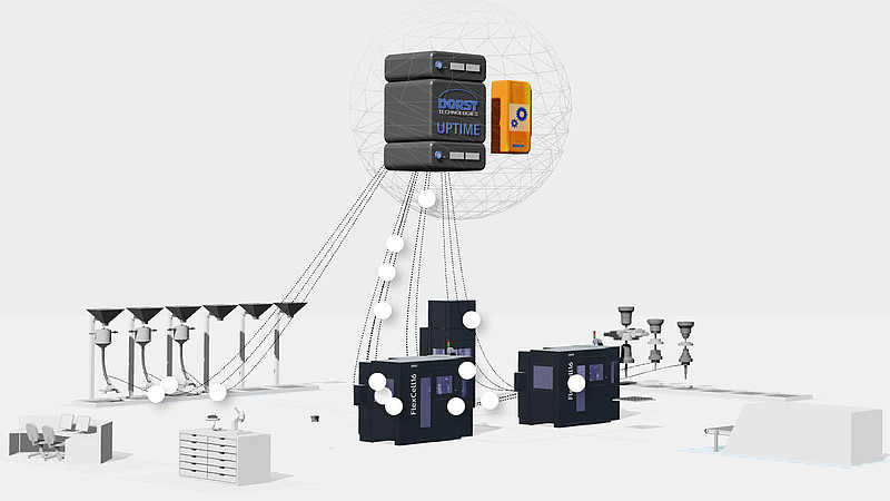
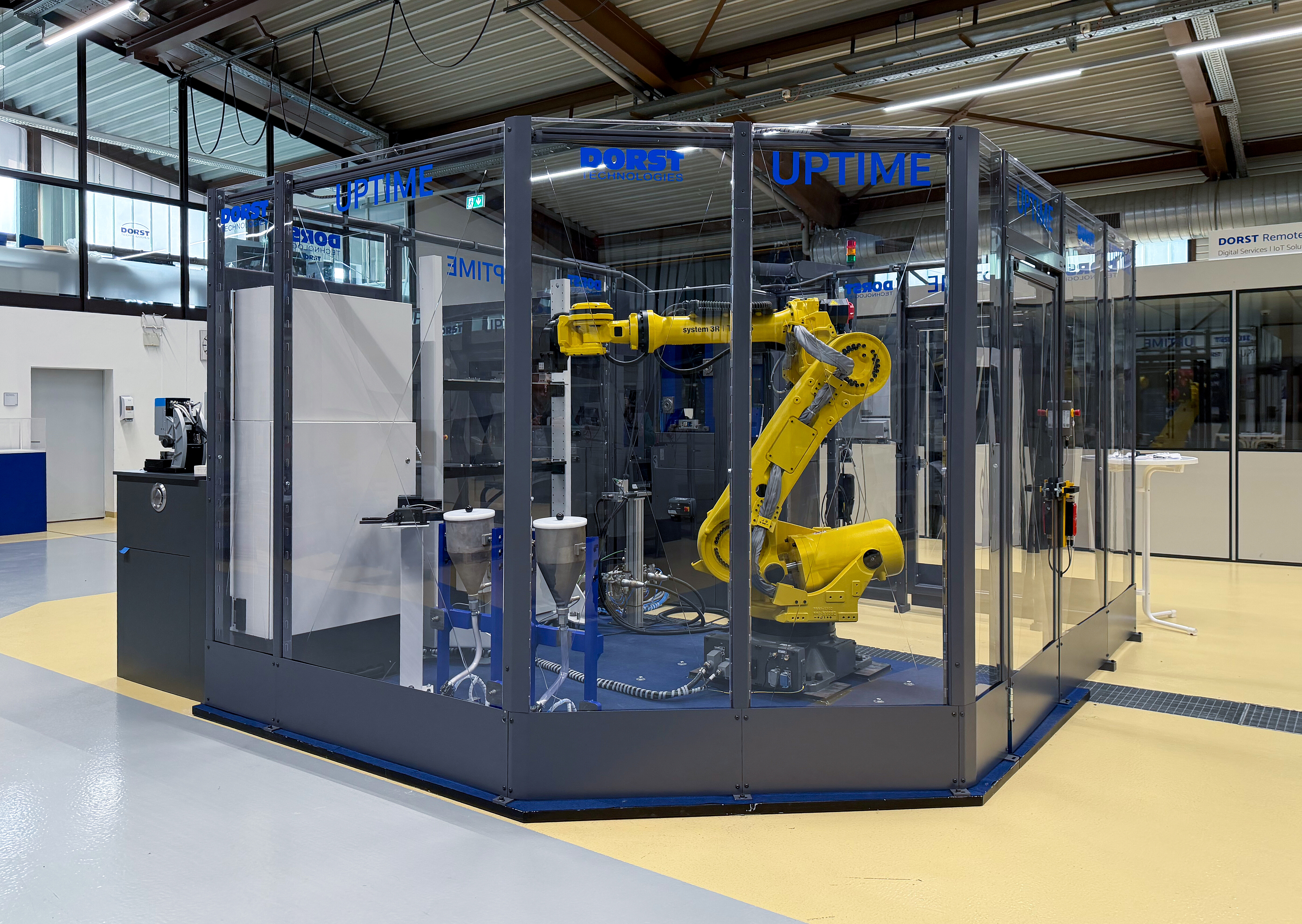
The concept is based on a production cell in which the press, robot, tooling magazine, powder system magazine, cleaning equipment and control system operate as an integrated unit.
Rather than treating the part changeover as a separate manual procedure, UPTIME brings it under the control of the production cell.
In this configuration, the robot carries out the handling steps required for tooling and powder system exchange, while the press control system coordinates the sequence and verifies the relevant machine states. The aim is to make
changeover more repeatable, reduce dependence on operator availability and support more flexible use of press capacity.
A production cell capable of automated changeover is better-suited to environments where smaller batches and more frequent part changes are required.
It can also support extended operating periods, including night or weekend production, where staffing levels may otherwise limit production planning.
The UPTIME concept can be applied across the EP press range.
It is particularly closely aligned with the FLEXCELL series, where the press and automation equipment are combined within an integrated production cell. FLEXCELL systems include functions such as part removal, sintering plate management, quality assurance and process monitoring as part of the cell concept.
The FLEXCELL range covers fully electric presses from 16 to 200 tonnes. In combination with UPTIME, it provides a reference platform for automated part changeover within a broader automated productionenvironment.
However, FLEXCELL is not a mandatory prerequisite; the UPTIME architecture can be adapted to different EP press configurations depending on the application.


The building blocks of an UPTIME cell
A typical UPTIME configurationconsists of seven main elements as seen in Fig. 4:
(1) the press with standardised interfaces for automated tooling change;
(2) the interchangeable powder system, including the hopper, hoses and fill shoe;
(3) powder system and
(4) tooling magazines managed through DVS2.0;
(5) a programmable cleaning unit;
(6) the robot handling system; and
(7) a gripper magazine enabling automatic end-effector changes according to the task. The exact layout is adapted to the application, tooling, material flow and available production space.

Technical requirements for automated changeover
Quick-change systems: precision as the foundation Automated part changeover depends on tooling and powder feeding systems that can be released, removed, reinstalled and clamped in a controlled and repeatable way.
In the UPTIME concept, the tools and powder feeding system are held by pneumatic quick-change clamping systems integrated into DVS2.0.
The controller manages the clamping and release sequence via defined signals and receives feedback on the clamping status.
The next robot command is only released once the required clamping state has been confirmed.
This provides a controlled interface between the press, tooling system and robot.
Repeatability is central to this approach. Each component must return to its defined position after removal and reinstallation, whether this concerns the tool holders or the powder system coupling.
The exact quick-change system, clamping arrangement and sizing are selected according to the application, tooling design and production requirements as part of the UPTIME engineering process.

Robot requirements
Robot selection is determined by the dimensions, weights and access conditions of the production cell.
In a typical UPTIME application, three requirements are particularly important: payload capacity, repeatability and mechanical access to the press workspace.
First, the robot must have sufficient payload capacity for the heaviest handling task.
A fully loaded hopper assembly, particularly in applications involving dense powders such as tungsten carbide, can be heavy and may shift its centre of gravity during movement.
The robot must therefore be able to handle the load safely and accurately under dynamic conditions.
Second, positioning repeatability is important when handling tooling components. Inaccurate seating ofpunches or other tooling elements can affect dimensional accuracy and, in severe cases, increase the risk of tool damage.
For this reason, a ±0.05 mm robot repeatability is used as the reference requirement.
Third, the robot must be able to access confined areas within the press. Payload alone is not sufficient;
wrist geometry, axis flexibility and reach all influence whether the robot can remove and install tooling reliably within the available space.
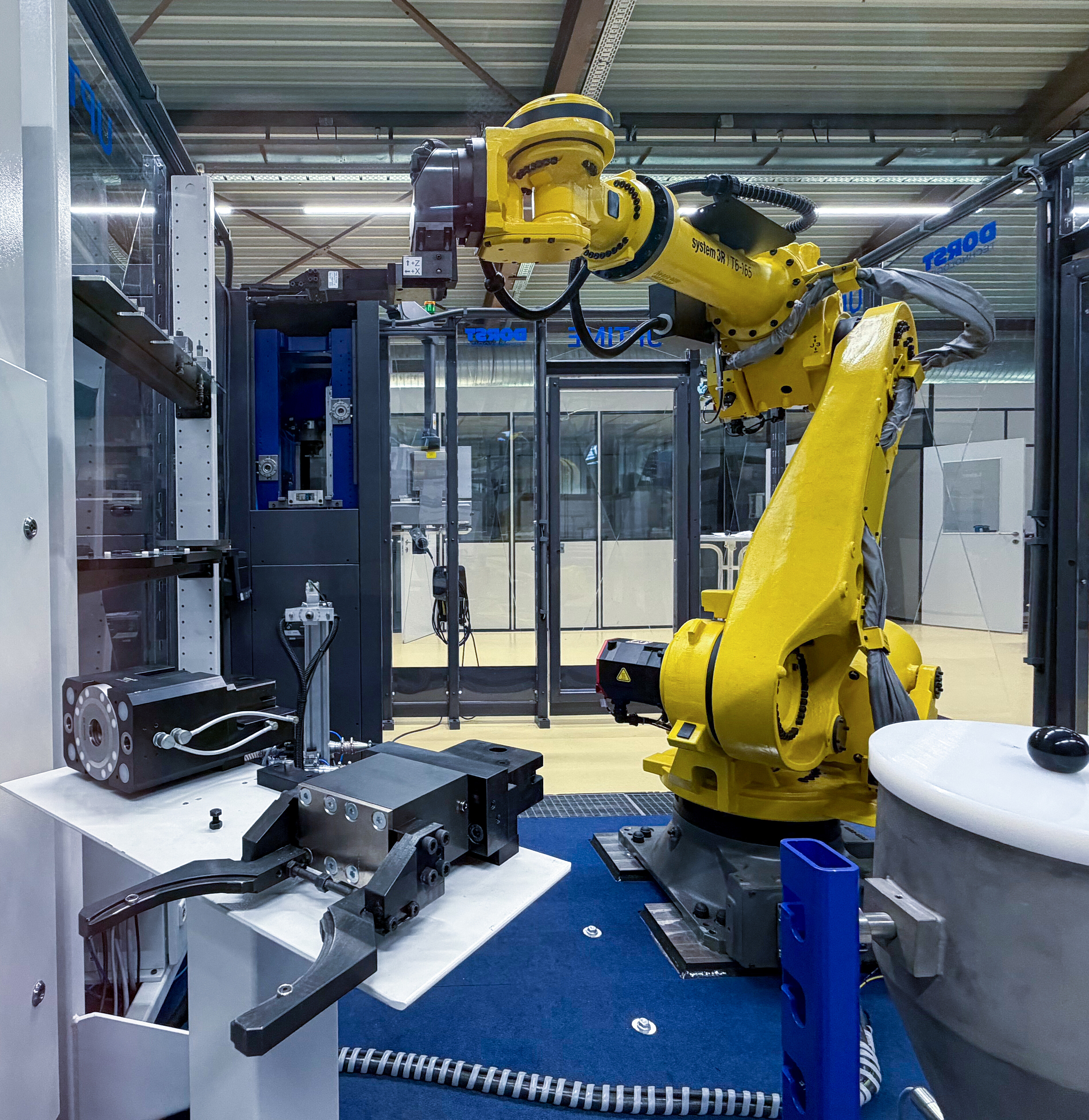
In the Dorst Technologies test setup, a six-axis heavy-duty robot with a 165 kg payload, 2,655 mm reach, slender wrist design and flip-over capability was used.
These figures describe the test configuration and indicate the required performance profile, rather than specifying a single robot make or model. Final robot selection is based on the application and cell layout.
How the automated changeover sequence works
Automated part changeover is divided into two main phases: disassembly and assembly. Both are coordinated by DVS2.0, which manages the interaction between the press, robot, tooling magazine, powder system magazine and cleaning equipment.
During the sequence, the press moves to defined positions, confirms machine states and releases handling steps in a controlled order
The robot then performs the required removal, cleaning, storage, retrieval and installation operations according to the programmed sequence.
This structure is intended to make the changeover process repeatable and traceable, while reducing reliance on manual intervention.
Phase 1: Disassembly
Decoupling the fill shoe
The part changeover sequence begins when the higher-level system, such as the control centre, Manufacturing Execution System (MES) or Enterprise Resource Planning (ERP), sends the changeover command to the press.
The press then enters tooling change mode. The servo-electric drive moves to the defined park position, and the fill shoe is pneumatically decoupled from the filler fork.
Once this step is complete, the press signals that the feeding unit is ready for removal.
Removing the powder feeding system
The robot removes the complete powder feeding system, including the hopper, fill shoe and filler plate, as a single assembly.
Theremoved assembly is assigned to a defined position in the powder system magazine. This allows the controller to identify where each powder system is stored and which subsequent production job it is associated with.
Optional cleaning step
Where required, the robot picks up the Cleaning Unit from the gripper magazine and performs a programmed cleaning cycle.
The cleaning path, contact pressure, suction output and number of passes can be adapted to the press geometry, powder material and production requirements.
Removing the upper punch
The press moves to the defined upper punch change position and confirms readiness.
The robot then removes the upper punch and places it in its coded position within the tool magazine.
The tooling inventory in DVS2.0 is updated accordingly.
Removing the die
The press moves to the lower tooling change position and confirms readiness for the next handling step.
The robot first removes the die and stores it in the tool magazine.

The coded storage system allows the controller to track each tooling component and its associated production job.
Removing the lower punch and core rod
In a second step, the robot removes the lower punch and core rod as a complete unit and places it in the tool magazine.
The coded storage system allows the controller to track each tooling component and its associated production job.
Optional cleaning after disassembly
After the tooling has been removed, the robot can again use the Cleaning Unit to clean exposed functional surfaces, including tool holder seats, guide surfaces and bearing faces.
This step helps ensure that the next tooling set is installed on clean and defined mating surfaces.
Phase 2: Assembly
Assembly follows the reverse sequence. At this stage, the required tooling and powder feeding system have already been identified from the job data supplied by the higher-level system.
The relevant components are registered, coded and stored in known magazine positions, allowing DVS2.0 to coordinate the installation sequence.
Installing the lower tooling set
The robot retrieves the coded tooling set from the tool magazine and installs the lower punch, die and core rod in the press.
Once the tooling set has been installed and the required machine state has been confirmed, the press signals readiness for the next step.
Installing the upper punch
The robot retrieves the upper punch and seats it in the tool holder.
The press then carries out the required referencing of the upper punch axis before the sequence continues.
Installing and coupling the powder feeding system
The robot retrieves the preconfigured powder-feeding assembly from the powder system magazine and installs it in the press.
The required material connections are established during this step.
The press then moves the filler fork to the fill shoe and pneumatically couples the system, completing the automated changeover sequence.
Preparing the press for production restart: DVS2.0 takes over
Once the mechanical changeover is complete, the Uptime_Data interface transfers the process data for the next job to the press controller.
This includes information such as partgeometry, tooling configuration, material parameters and the production programme.
DVS2.0 then carries out the required referencing of the press axes and prepares the machine for production.
Before release, the system verifies that the relevant data and machine states are in place, reducing the need for manual input at production restart.
Benefits of a standardised changeover process
Compared with a manual changeover, the key difference is that the sequence is standardised and controlled by the production cell.
Each step is carried out in the defined order, using the same machine positions, handling procedures and verification points.
This reduces the extent to which the outcome depends on the individual operator, shift or time of day.
For manufacturers, the intended result is a more predictable changeover process, improved restart consistency and greater flexibility in production planning.
Scaling UPTIME across multiple presses
The UPTIME concept can be implemented as an individual automated production cell or scaled across a press line.
In a line configuration, one robot may service multiple presses in alternating operation.
While one press is producing, the robot can carry out a changeover on another press, helping to improve utilisation across the line.
This approach is intended to support continuous production planning, particularly in environments with frequent changeovers or extended operating periods.
For companies wishing to evaluate the concept before implementation, Dorst Technologies has a fully equipped UPTIME cell at its technology centre in Kochel am See, where customer tooling, materials and processes can be tested.
Mobility option A: robot on a linear track
One approach is to mount the robot on a floor-level linear track, also referred to as a seventh axis. This allows the robot to travel between presses arranged in a line and perform changeover tasks at each station. A typical system uses a rackand-pinion drive in combination with hardened recirculating ball guides or profiled rail guides. This arrangement is suited to high system loads and longer travel distances, while providing controlled positioning along the press line. The additional axis is integrated into the robot controller, allowing the travel movement and robot arm motion to be coordinated within the programmed sequence. A key engineering consideration is the bending moment created by the robot arm and payload when extended from the carriage. For this reason, the track, carriage and guide system must be designed with sufficient stiffness and accurately preloaded guide elements. The main layout requirement is that the presses are arranged in a linear configuration, allowing the robot to access each cell position along the track (Table 1).
| Property | Linear track |
|---|---|
| Positional accuracy | Very high ±0.05 to ±0.1 mm, mechanically referenced |
| Cycle time | Precisely calculable; simultaneous arm and travel motion possible |
| Infrastructure | Floor-level rail installation, torsionally rigid modular design |
| Layout requirement | Linear press arrangement required |
| System load | Up to 1,500 kg (robot + payload), travel up to 30 m |
| Maintenance | Low - centralised lubrication, long-life guides |
| Investment reliability | Very high - Established technology with extensive industrial use |
Table 1 Technical characteristics of a robot linear-track system for automated press changeover
Mobility option B: robot on AMR
Where the production layout does notallow a straight press line, an Autonomous Mobile Robot (AMR) can serve as an alternative carrier platform for the robot.
This approach gives the system greater freedom of movement within the factory and eliminates the need for a fixed-rail installation.
An AMR can navigate using technologies such as LiDAR, cameras and mapping software.
This enables it to move between different production areas without the need for floormounted guidance systems or fixed markers.
In this configuration, the AMR may also be used for related logistics tasks, such as transporting tooling, powder systems or other production equipment between storage and the press area.
For automated tooling change, however, the positioning requirements are significantly higher than those needed for general factory transport.
The travel accuracy of an AMR alone is typically insufficient for precise tool installation.
Additional fine-positioning systems, such as optical markers, camera-based correction or mechanical docking fixtures, are therefore required to bring the robot into the exact position needed for changeover operations.
The AMR option is most relevant when layout flexibility is a priority or when presses and storage areas are not arranged in a fixed linear sequence. It introduces additional positioning and control requirements but can provide greater adaptability in facilities where a linear track is impractical (Table 2).
| Property | AMR |
|---|---|
| Positional accuracy | High – with fine-positioning system |
| Cycle time | Good – depends on route profile and utilisation |
| Infrastructure | No fixed guidance infrastructure required |
| Layout requirement | Any factory layout possible |
| Navigation | Free routing, curves included |
| Additional benefit | Entire facility usable; logistics tasks integrable |
| Investment reliability | High – Increasingly adopted in industrial automation |
Table 2 Technical characteristics of an AMR-based robot system for automated press changeover
Decision framework: linear track or AMR?
The key differences between the two mobility concepts are summarised in Table 3.
Both mobility concepts can be integrated into the UPTIME architecture.
The choice between a linear track and an AMR mainly depends on the production layout, required flexibility and positioning strategy.
In both cases, the underlying press integration and software architecture remain the same.
| Criterion | Linear track (7th axis) | AMR |
|---|---|---|
| Factory layout | Linear arrangement required | Any layout possible |
| Positional accuracy | Very high, mechanically referenced | High, with fine positioning |
| Cycle time | Precisely calculable | Good, route-dependent |
| Layout flexibility | Low | High |
| Additional benefit | Limited to the rail path | Entire facility usable |
| System complexity | Low | Medium (fine-positioning required) |
| Proven track record | Very high | High, growing references |
Table 3 Comparison of linear-track and AMR mobility concepts within the UPTIME architecture
Software integration: DVS2.0 as the control backbone
DVS2.0, Dorst’s control and visualisation system for the EP press range, provides the software backbone for the UPTIME cell.
In this architecture, the robot is integrated directly into the press control environment.
It receives its commands from DVS2.0 and operates as part of the coordinated production cell rather than as a separate automation unit.
The system hierarchy begins with a higher-level control system, such as a control centre, MES or ERP.
This system issues the part changeover command and provides the relevant job, tooling, material and planning data.
The press receives this information via the Uptime_Data interface, and DVS2.0 then coordinates the changeover process.
Based on the job data, DVS2.0 identifies the required tooling set, locates it in the magazine and guides the robot through the defined sequence.
Once the mechanical changeover has been completed, the system references the required axes, loads the production programme and prepares the press for production release.
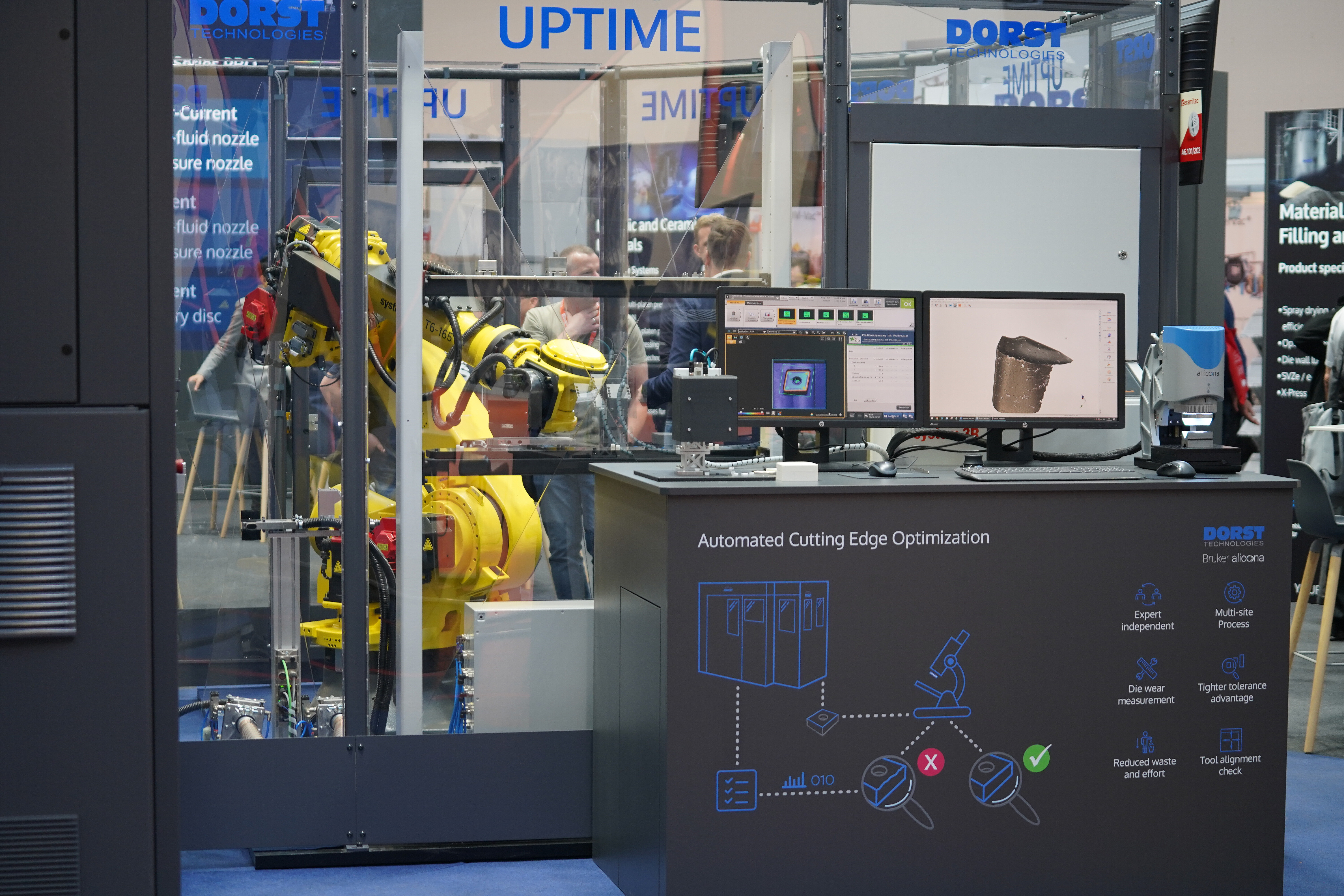
The DVS2.0 visualisation provides the operator with an overview of cell status, job progress and relevant system information.
Operator interaction s focused on order planning, status monitoring and any required acknowledgements.
New robot motion sequences can be taught at the machine using a dedicated handheld device and then stored for automated execution.
Tooling and powder system management are handled through coded inventory within DVS2.0.
This allows the system to track which tooling sets are available, where they are stored and which production jobs they are assigned to.
Standardised interfaces also allow connection to higher-level MES or ERP systems.
In combination with the Dorst IoT Field Manager, process, machine, tooling and robot data can be made available for monitoring and analysis, providing a basis for maintenance planning and process optimisation.
“Reducing changeover time directly affects press availability.
Every minute spent on setup is time during which the press is not producing parts.
A more controlled and automated changeover sequence can therefore improve machine utilisation, particularly in high-mix production environments.”
What UPTIME delivers
Reducing changeover time directly affects press availability.
Every minute spent on setup is time during which the press is not producing parts.
A more controlledand automated changeover sequence can therefore improve machine utilisation, particularly in high-mix production environments.
By automating the sequence, UPTIME is designed to reduce the waiting times, interruptions and manual handling steps that can occur during conventional changeover.
It also reduces the amount of skilled labour required at the press during setup.
This allows experienced personnel to be deployed on tasks such as tooling preparation, quality assurance, process optimisation and production planning.
The standardised, robot-guided sequence is intended to improve repeatability at production restart.
Defined cleaning steps, controlled tooling installation, verified clamping states and transferred process parameters all contribute to a more consistent setup condition before production resumes.
This can help reduce startup variation and lower the risk of scrap linked to manual changeover errors.
Automated changeover also supports more flexible use of press capacity.
Where changeovers can be carried out more efficiently and with less dependence on operator availability, manufacturers are better placed to plan smaller batches, accommodate part variety and make greater use of extended production periods, including nights and weekends.
In this way, UPTIME contributes mnot only to shorter setup times, but also to broader production flexibility, improved process consistency and more predictable machine utilisation (Table 4).
| Value driver | Effect |
|---|---|
| Shorter changeover times | More productive press hours per shift and per day |
| Reduced setup labour requirements | Skilled staff available for value-adding tasks |
| Reduced startup scrap | Verified parameters before production restart and reduced setup variation |
| 24/7 production | Machine utilisation independent of shift schedules and staffing |
| Improved compliance support | Automated handling minimises exposure to hazardous powders |
| New market opportunities | Small batches and high variety become economically viable |
Table 4 Production and operational benefits associated with automated part changeover using UPTIME
Outlook: towards more automated powder pressing
UPTIME forms part of Dorst Technologies’ wider automation strategy for powder pressing.
By bringing part changeover into the controlled sequence of the production cell, the concept addresses one of the key interruptions in conventional press operation: the manual changeover between tooling sets and powder systems.
For manufacturers, this has implications beyond just setup time. Part changeover affects press utilisation, labour requirements, process stability and productionplanning.
As batch sizes decrease, part variety increases, and skilled labour becomes harder to secure, a more repeatable, automated changeover process can support greater flexibility across the production environment.
The concept is continuing to develop as different automation Automated product changeover scenarios are tested and prepared for industrial implementation.
A fully equipped UPTIME cell is available at Dorst’s Technology Centre in Kochel am See, where customer tooling, materials and processes can be evaluated before an investment decision is made.
In this context, automated part changeover represents a practical step towards more autonomous powder pressing operations.
It reduces dependence on manual intervention, improves the repeatability of setup procedures and supports more predictable use of available press capacity.
Author
Alexander Blankenhagen
Area Sales Manager
Carbide & Special Materials
Dorst Technologies GmbH
Mittenwalder Str. 61
82431 Kochel am See
Germany
www.dorst-technologies.com
Published in the Summer Issue 2026 of Metal Powder Technology